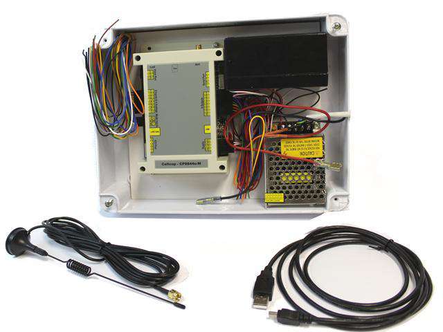
The Cellcop GSM communicator system is based on SMS and GPRS technology. It uses standard cellphone technology for communication and has been designed to provide you with the greatest possible flexibility and convenience. Read this manual carefully and have your installer instruct you on your system’s operation and on which features have been implemented in your system. All users of this system should be equally instructed in its use.
The cellcop communicator can be used in various applications to monitor and control system alarms and parameters remotely using your cellphone. The unit can be configured to your requirements by using the configuration tool. The configuration tool allows the user to setup various options by setting the parameters and sending the setup to the cellcop. Using the configuration tool you can setup the Cellcop directly using a USB cable connected to the to the cellcop or remotely by connecting a GSM modem to the PC running the configuration tool and connect to the cellcop using a data call. The configuration can be backed up to a file using the configuration tool, for easy reuse in future or quickly setting up multiple boards with the same configuration.
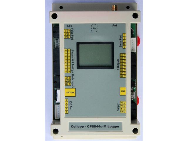
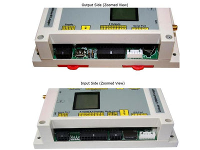
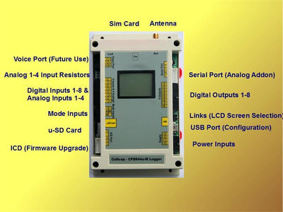
8 Inputs to communicate separate alarm conditions
- Each input can be triggered to send an SMS to up to 16 Cellphone numbers
- The time delay before the input is triggered can be set for each input
- Separate messages can be configured for On and Off states of the input signal
- Messages to be send can be programmed by the user
- On or Off states can both be reported to predefined cellphone numbers.
- Reporting can be disabled for an input
- The states of the inputs can be requested from the unit by SMS
- Monitoring of the inputs can be controlled using different modes
- Inputs can act as counters
- Inputs can act as Run Hour meters
4 Analog Inputs
- Each analog input can perform a analog measurement and report 2 High alarmsand 2 low alarms per input.
- Time delay can be configured for each alarm
- Analog alarm levels can control relay outputs to enable analog control functionality.
- Analog changes can be logged to a server via GPRS communications.
8 Outputs to control any electrical device
- Outputs can be controlled by cellphone using SMS on, off or pulse
- Output controls can be scheduled
- The duration of the pulse can be programmed for each output
- Outputs can be set to follow the state of an input
- Output can be set to switch on when the unit is dialed
- Status of an output can be requested from the unit by SMS
- Analog Limits can control the switching of outputs
- Own text can be used to control outputs
Monitor AC power using the charger input
- AC power can be monitored by using the charger input.
- SMS can be send to up to 16 numbers when an power failure occur and when the power return
Monitor the battery status
- The battery status can be monitored by the system.
- SMS can be send to up to 16 numbers when the battery go faulty.
- The battery is monitored by disconnecting it from the main supply and to measure the battery voltage while connected to a load.
Remote Program Commands via SMS / GPRS * The setting of configuration parameters remotely by SMS or GPRS.
Remote Control Program Commands via SMS / GPRS
- The execution of Control Commands remotely by SMS or GPRS.
Scheduled Commands
- The execution of commands can be scheduled
SD Card Logger
- The system will log events configured to be logged
- Logged events will be time stamped from the Cell phones Date/Time
- Events can be downloaded into a comma delimited file for analysis
Monitor Mode
- Monitor mode is used to activate monitor functions
- Monitor Mode can be set by SMS or Monitor mode Inputs
LCD Add on
- Display Status information on LCD display
- Multiple pages on LCD Display
- Pages configurable to user requirements
Custom Status Message
- Custom status reply messages can be configured
Configuration tool to configure unit to user requirements
- All parameters can be set from configuration tool.
- Remote programming possible from the configuration tool
- Save and Load from files for backup